2015 thesis project

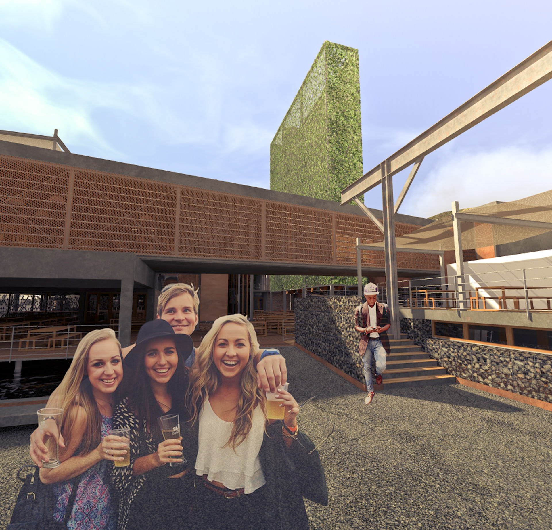
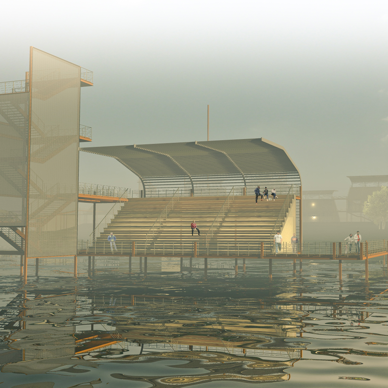
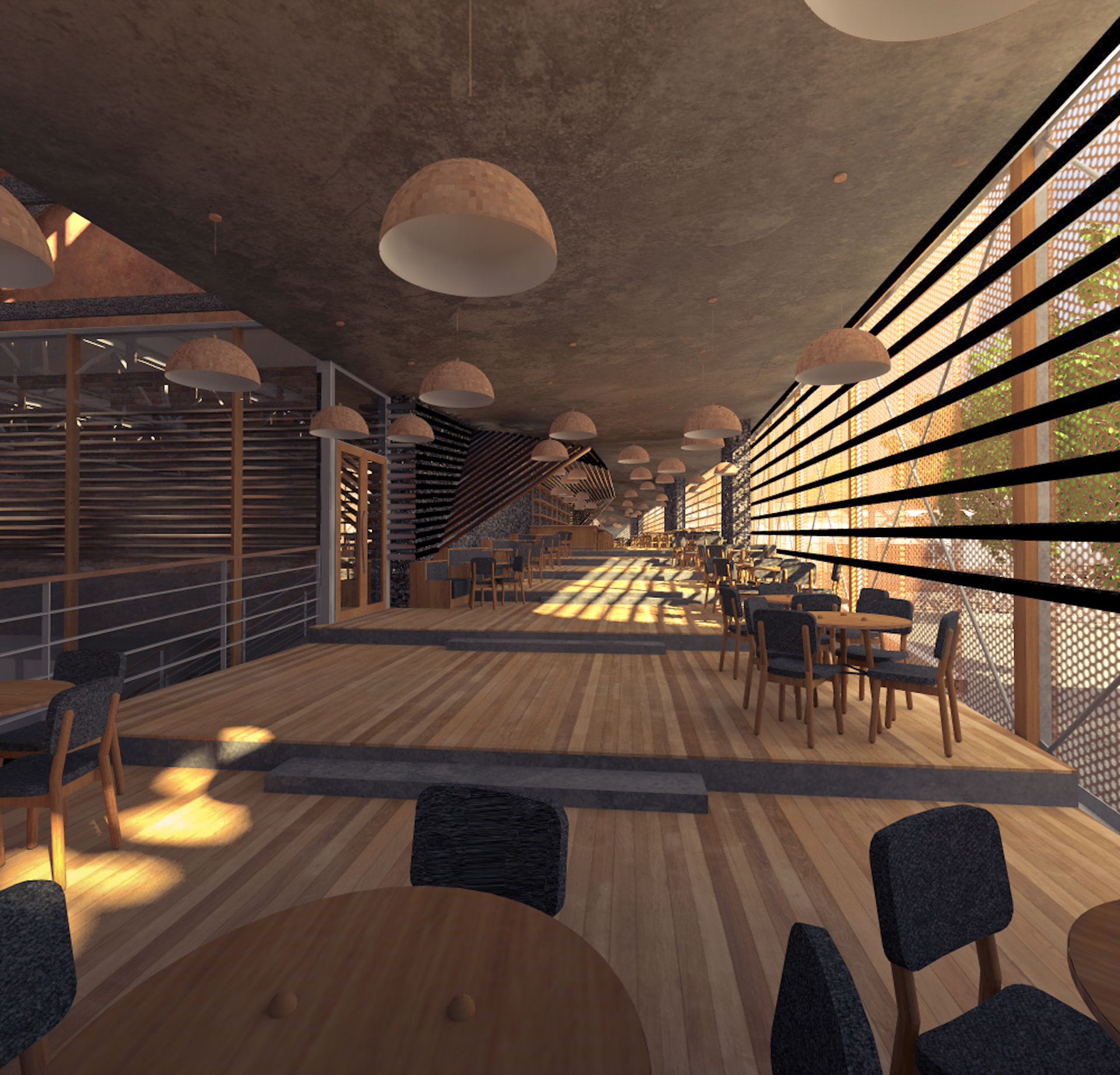
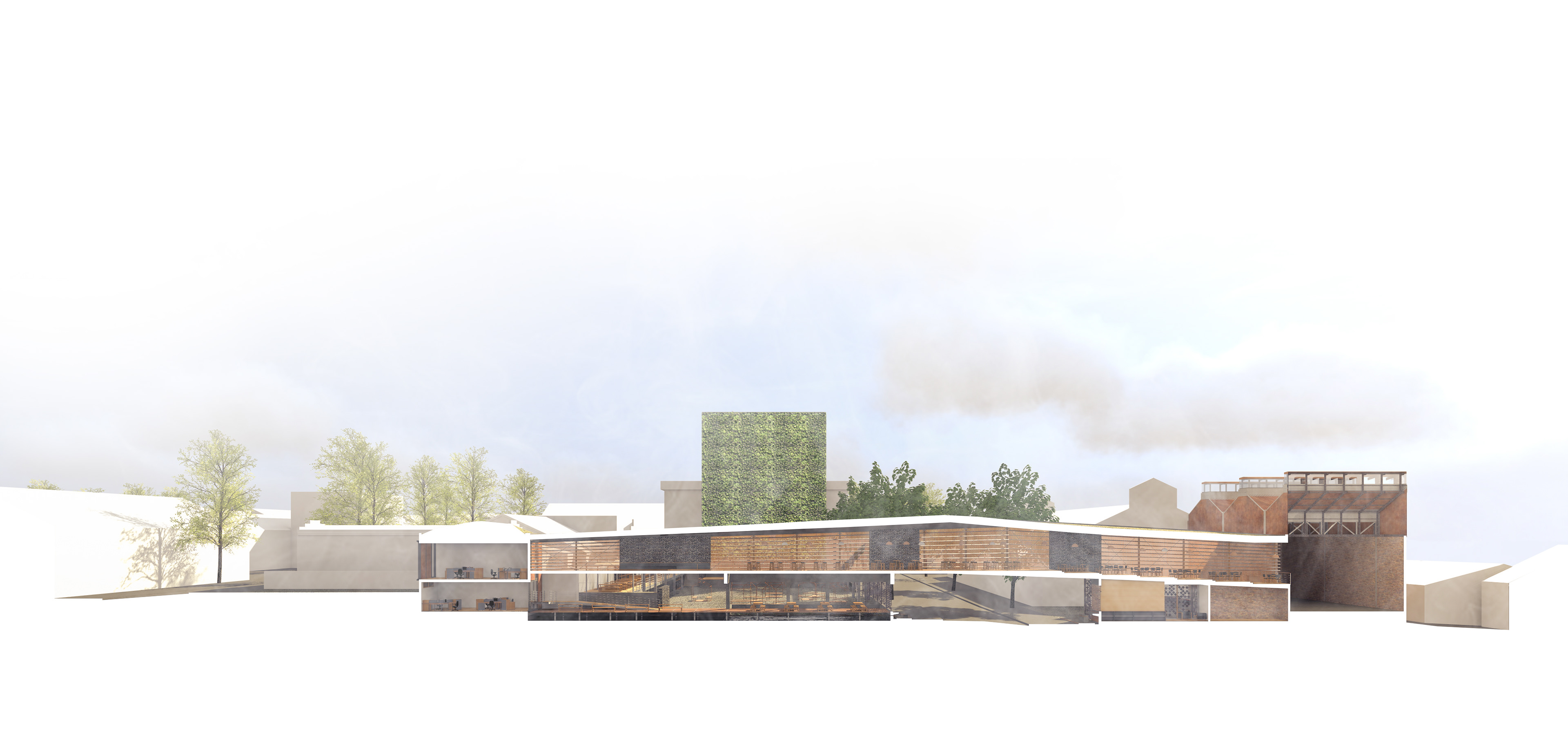
The bridge is the most prominent element in the building’s composition. It is an allegory to the brewery’s purpose of connecting people, and a bold expression of the building’s internal functions to the street. It stands over the pedestrian approach to the building, and houses the main bar, with seating looking out over the road and the events courtyard. This is one of the most active, social spaces in the building and revelrous shadows will be seen dancing above the street, an early enticement to visitors to join the party, especially at night when the entire length of the bridge will be lit from within.
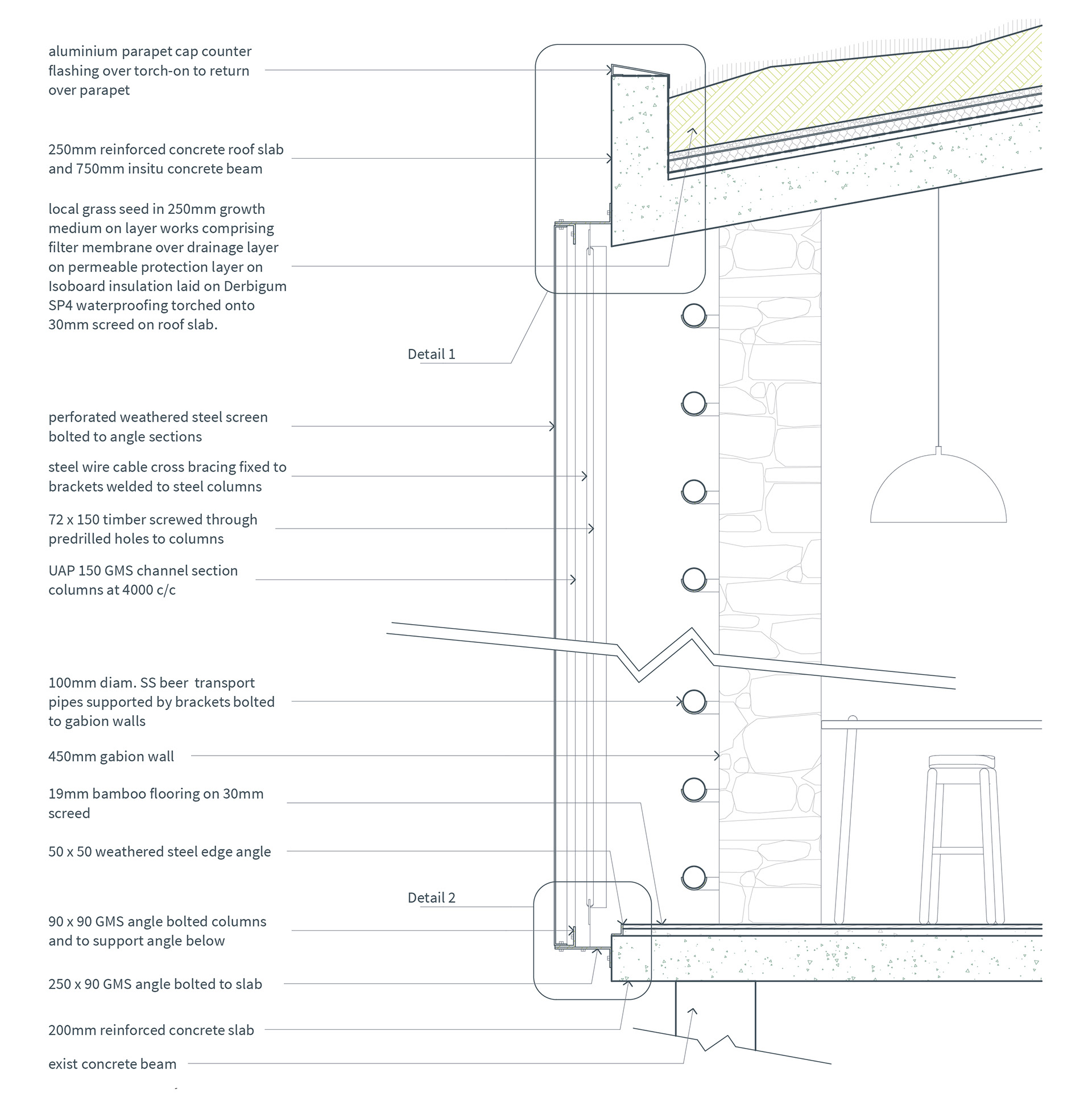
The bridge’s face is turned towards the west, from where Johannesburg’s predominant winds blow, and a source of late afternoon sun. The facade on this edge is wrapped in a perforated screen of oxidised steel supported by a braced steel structure. Behind this is a layer of stainless steel pipes which transport the beer throughout the facility, and a series of deep gabion walls which support the roof and provide thermal mass.

The perforated screen allows for ventilation through the bar and the restaurant and brewery beyond it while buffering any strong winds. The temperature of the air is then regulated by circulating hot or cold liquid through the pipes as part of a larger system, including the cooking equipment and stormwater drains, which serves to heat and cool the spaces inside the building, and conversely cool or heat the beer itself as part of the brewing process, sharing energy throughout the building.
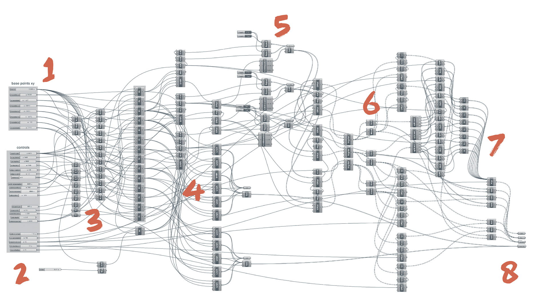
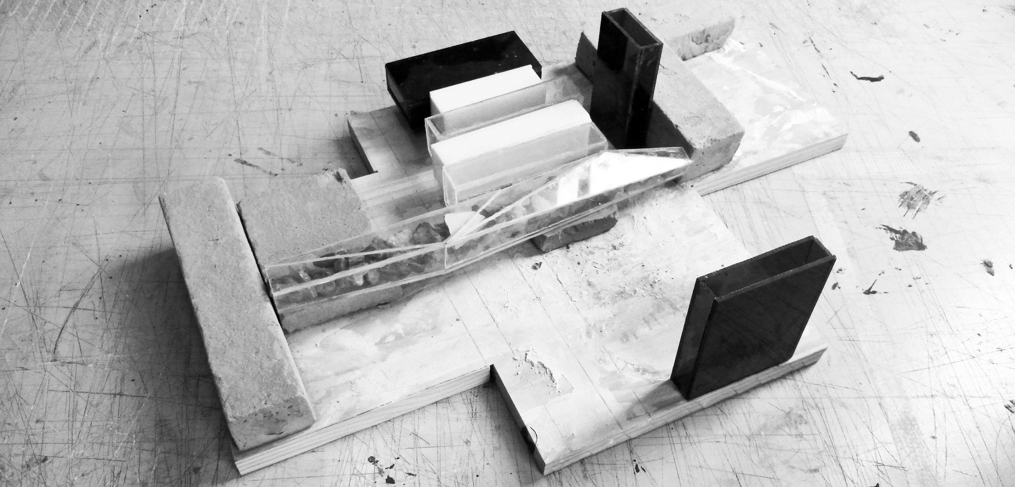
I set up the basic parameters (1) for the bridge’s form by creating a set of xyz points which corresponded with the points at which it needed to meet its neighbouring structures. I then created a second set of points so that the height could be adjusted at each corner parametrically. (2) Next, I developed some functions to adjust some other major aspects of the mass – the distance to which the mid-point could extend, the roof overhangs, the widths of the openings at either end, and the slope of the northern half which would run down to the building’s entrance. (3) I could then manipulate the mass to find the form which I felt best suited the building’s composition, baking multiple iterations into Rhinoceros to compare. With the basic bounding box established, I then isolated the points for each face and created a series of surfaces which would become the starting point for a set of scripts for each individual face (4) – solid slabs for the floor and roof, and a light, perforated screen wrapped over the vertical faces. I modelled the screen itself last, in ArchiCAD, but decided that Grasshopper would be the best tool for developing the cross-braced column structure behind it.


I used a plugin for Grasshopper called Lunchbox, which has specialised tools for creating grid structures on surfaces, to break each wall up into a series of vertical divisions at a set interval of about four metres. (5) These would be the armatures on which I would build the bridge’s columns. I sketched out my design for the columns by hand (previous page) and proceeded to draw the outline for the steel and timber elements of the construction separately, which I could then copy on to each vertical division in the existing Grasshopper definition, and then extrude. To tidy up the overall definition, I packaged these sets of actions into batteries for steel and wood. (6) Finally, all that was left to do was create the cross-bracing members between the columns. Each column was designed with a set of flanges on to which to fix the cables for bracing. I defined a point in the middle of each flange and then connected the relevant points with lines on which I ran a simple pipe command to give weight to the cables. (7) Each element had to be consolidated into individual breps (8) so that they could be exported to ArchiCAD.